Original Link: https://www.anandtech.com/show/16248/edsff-form-factor-updates
EDSFF Form Factor Updates In 2020: New Versions, Growing Adoption
by Billy Tallis on November 25, 2020 5:00 PM EST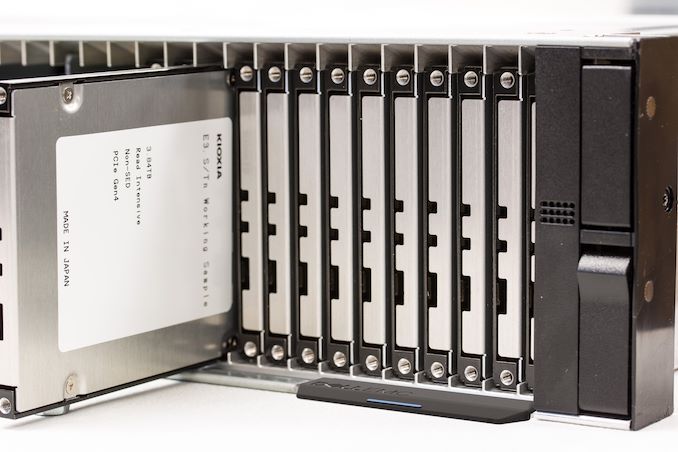
The Enterprise and Datacenter SSD Form Factor family of standards is now about three years old, and continues to evolve. The EDSFF form factor options are gaining traction in several markets, and lessons learned by early adopters are still driving tweaks to the specifications. The myriad variations under the EDSFF umbrella have not been simplified much, but at least the brief format war between the EDSFF E1.S form factor and Samsung's NF1 has concluded, with Samsung now supporting and contributing to the E1.S standard. As EDSFF adoption increases, we'll probably see several variants fall into irrelevance, as happened to some of the less popular M.2 card sizes. But even once it's clear which members of the EDSFF family are succeeding in the market, the less popular options will probably remain part of the standards documents.
The EDSFF flavors all share a common connector standard, which originated as the Gen-Z Scalable Connector Standard and has been adopted by several other standards. The Gen-Z connector provides much higher density than traditional PCIe slots, supplies the 12V power that M.2 lacks, and is relatively future-proof by offering adequate signal integrity for future versions of PCIe. The EDSFF standards define three sizes of the connector and pinouts for PCIe x4, x8 and x16 links.
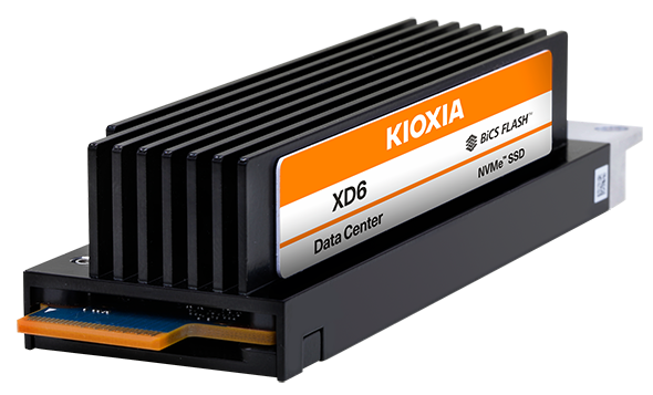
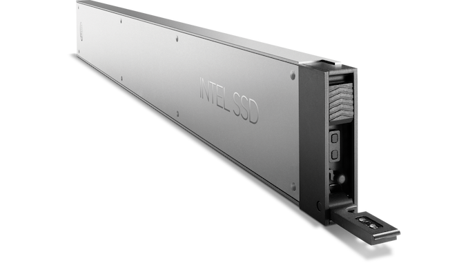
The EDSFF form factors come in two heights: sized for 1U servers are E1.S and E1.L, the short and long derivatives of the Intel Ruler concept. For 2U servers, the E3 sizes are similar to the existing 2.5" drive form factor.
Reboot Of E3
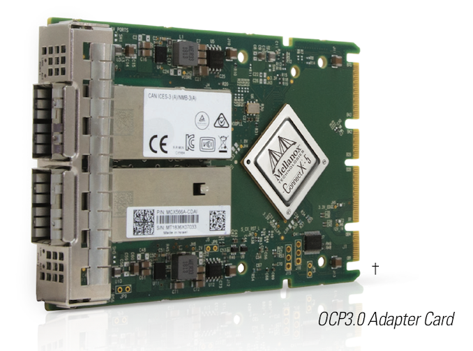
The most significant changes in the past year were to the E3 form factors. Earlier this month version 2.0 of the E3 form factor spec was published, breaking backwards compatibility with version 1.0 from 2018. The motivation for the incompatible changes came from the Open Compute Project (OCP) NIC 3.0 specification, which has similar dimensions but uses a new variant of the Gen-Z connector: OCP added a fourth tab with 28 extra contacts to carry various sideband signals not included in the 4c (x16) version of the connector. The E3.S form factor was stretched a bit to match the dimensions of the OCP NIC 3.0 standard, and the connector location was moved to be compatible with the OCP NIC 3.0. With the new version of the EDSFF E3 spec, it's now possible for servers to provide slots that can fulfill either role.
The E3 form factors are the most capable and flexible in the EDSFF. They support up to PCIe x16 connections, though most SSDs will continue to stick with just x4. The E3.L 2T offers similar physical volume and TDP to a half-height half-length PCIe add-in card. The E3.S in two thicknesses is slightly larger than the two common thicknesses for U.2/U.3 SSDs, but E3.S offers better cooling and the possibility of more PCIe lanes. The newly stretched E3.S is also now large enough that an E1.S PCB can be mounted inside an E3.S case, providing a quick and easy path for compatibility between the two heights.
| E3 version 2.0 Form Factor variants SFF-TA-1008 |
|||||||||
| Form Factor | Approximate Dimensions (mm) |
Front Drive Bays in 2U |
Typical SSD Power Limit |
Max PCIe Lanes |
|||||
| E3.S | 76 | 113 | 7.5 | 48 | 25 W | x16 | |||
| E3.S 2T | 76 | 113 | 16.8 | 24 | 40 W | x16 | |||
| E3.L | 76 | 142 | 7.5 | 48 | 40 W | x16 | |||
| E3.L 2T | 76 | 142 | 16.8 | 24 | 70 W | x16 | |||
| PCIe HHHL | 68 | 168 | 19 | 40-75 W | x16 | ||||
| 2.5" U.2 | 7mm | 70 | 100 | 7 | 48 | 12 W | x4 | ||
| 15mm | 70 | 100 | 15 | 24 | 25 W | x4 | |||
| 3.5" U.2 (theoretical) | 102 | 147 | 26 | 12 | x4 | ||||
| M.2 22110 | 22 | 110 | 5 | 8.25 W | x4 | ||||
When the EDSFF family launched, most of the early attention was focused on the E1.S and E1.L form factors because they addressed the most pressing needs of hyperscale datacenters. The E3 form factors are more attractive for traditional enterprise servers, which take longer to adopt changes like this. Dell and HPE are the leading proponents of this part of the EDSFF family. Since the E3 standard was just rebooted with an incompatible change, we're now looking at E3 version 2.0 products hitting the market around the first half of 2022.
Servers using E3 form factors are likely to use more than one version, such as providing a dozen or more thin slots for SSDs, plus several of the thicker 2T slots for NICs, accelerators, and higher-power SSDs (eg. based on 3D XPoint or some other storage class memory). While they are primarily intended for 2U systems, the E3 form factors can be used in 1U servers, but have some cooling and density disadvantages relative to E1.S for 1U systems.
E.1S In Production Use
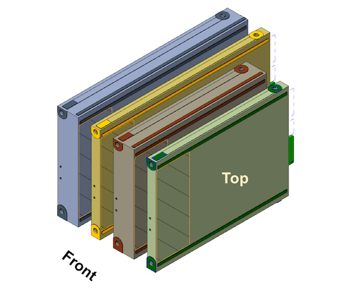
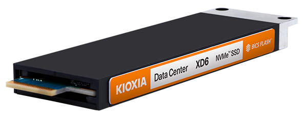
The E1.S family has now grown to include five different thickness options. However, the standards for a bare PCB or one with just a heatspreader are not getting much attention. The three (formerly two) versions with a full enclosure seem to be the most popular. These can slide directly into a hot-swap bay without needing to be screwed into a tray or caddy. At the front of the drive is a flange with two screw holes which are used to attach an appropriate latching mechanism for whatever server chassis the drives will be installed into. Samsung has recently proposed modifying this with a few extra cutouts to enable a screw-less version of their latching mechanism, which will be quicker to install.
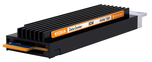
This year's addition to the E1.S standard was a new intermediate thickness heatsink option proposed by Microsoft and intended for their Azure datacenters. Microsoft found that the 9.5mm symmetric enclosure didn't offer quite enough cooling for the kind of drive TDPs they're expecting for PCIe Gen4 SSDs (at least, within the bounds of reasonable fan speeds), but the 25mm asymmetric enclosure/heatsink sacrifices a bit too much density and has excess thermal headroom that Microsoft doesn't need for their primary storage drives. As a result, there's now also a 15mm version standardized and already being deployed at scale.
| E1.S Form Factor variants SFF-TA-1006 |
|||||||||
| Form Factor | Approximate Dimensions (mm) |
Front Drive Bays in 1U |
Typical SSD Power Limit |
Max PCIe Lanes |
|||||
| E1.S | Bare PCB | 32 | 112 | 5.9 | 12 W | x8 | |||
| Heatspreader | 32 | 112 | 8 | 16 W | x8 | ||||
| Symmetric Enclosure |
34 | 119 | 9.5 | 36 | 20 W | x8 | |||
| Asymmetric Enclosure |
34 | 119 | 15 | 24 | 20 W | x8 | |||
| 34 | 119 | 25 | 16 | 25 W | x8 | ||||
| M.2 22110 | 22 | 110 | 5 | 8.25 W | x4 | ||||
| 2.5" U.2 | 7mm | 70 | 100 | 7 | 20 | 12 W | x4 | ||
| 15mm | 70 | 100 | 15 | 10 | 25 W | x4 | |||
| PCIe HHHL | 68 | 168 | 19 | 40-75 W | x16 | ||||
The 9.5mm-thick enclosure option was already sufficient to kill off server M.2 drives except for boot drive usage: it offers the hot-swap capability and 12V power that M.2 lacks, and can be deployed with similar density. The newer 15mm thick heatsink version of E1.S may end up being more popular, but it's a bit too new to judge how much traction it will get beyond the original proponents. Compared to 2.5"/15mm U.2 SSDs, the E1.S 15mm form factor is still a significant improvement: four E1.S 15mm drives can fit in the space of two 15mm U.2 drives, and the E1.S drives are still easier to cool. Storage-focused systems can achieve higher density with the 9.5mm option, but the E1.L form factors offer even higher storage density.
The 25mm heatsink E1.S option now seems likely to be the least popular of the three enclosure choices. It still has a niche for squeezing high-power accelerators into 1U systems, but PCB width can be a limiting factor and the E3 form factors can also accommodate big, high-power chips. Any E1.S slot providing 8 instead of just 4 PCIe lanes is likely to use at least the 15mm heatsink option, because an accelerator capable of using that much bandwidth will need the extra cooling.
All of the E1.S variants use the same PCB and vary only in the metal enclosure and height of the heatsink (if any), so there's not much burden on SSD vendors to support all three of the 9.5mm, 15mm and 25mm. Server vendors face the tougher choice of deciding how wide to make their slots; narrower drives can be mounted in wider slots, but this may lead to unbalanced airflow—though not as bad as leaving a slot empty without a placeholder inserted. The most common configuration for general-purpose 1U servers might end up being a bank of E1.S slots for storage plus one or two E3.S/OCP NIC slots—this seems especially likely if the OCP approach of putting all IO at the front of the server catches on outside of hyperscale datacenters.
E1.L Unchanged
There have been no recent changes to the E1.L form factor. This one remains the closest to Intel's original Ruler concept. It is much longer than any other drive form factor, so the entire server layout must be designed around E1.L. This form factor will be used almost exclusively in systems designed for the sole purpose of containing a lot of flash memory, and will not see any significant adoption for general-purpose or compute-oriented servers. E1.L is suitable for drives with capacities of tens of TB each.
| E1.L Form Factor variants SFF-TA-1007 |
|||||||||
| Form Factor | Approximate Dimensions (mm) |
Front Drive Bays in 1U |
Typical SSD Power Limit |
Max PCIe Lanes |
|||||
| E1.L | Thin | 38 | 319 | 9.5 | 36 | 25 W | x8 | ||
| Thick | 38 | 319 | 18 | 18 | 40 W | x8 | |||
| 2.5" U.2 | 15mm | 70 | 100 | 15 | 10 | 25 W | x4 | ||
| PCIe HHHL | 68 | 168 | 19 | 40-75 W | x16 | ||||
While not formally part of the EDSFF specifications, the Open Compute Project's storage working group has developed the OCP NVMe Cloud SSD specification. This is a unification of most of Microsoft and Facebook's requirements for their SSDs, covering areas like the optional NVMe features, telemetry capabilities, endurance and performance that those companies want. The Cloud SSD specification applies to M.2 22110, E1.S and E1.L form factors. Several SSD vendors are already targeting this specification, which will help cut down on the amount of firmware customization required by different customers.
Related Reading
- Intel Introduces "Ruler" Server SSD Form-Factor: SFF-TA-1002 Connector, PCIe Gen 5 Ready
- SSD Form Factors Proliferate At Flash Memory Summit 2018
- FMS 2019: EDSFF Form Factors Update - Long, Short, & Everything In-Between
- Kioxia Announces XD6 Datacenter SSDs: PCIe 4.0 and EDSFF At Scale
- Western Digital Unveils Ultrastar DC SN640 SSDs: Up to 30.72 TB Capacity


